Sludge treatment − centrifugal thickening

How centrifugal thickening works
Centrifugal thickening increases the sludge concentration (i.e. thickens the sludge) by encouraging the particles to migrate to the walls of a rapidly rotating cylindrical vessel under the influence of a centrifugal force.
There are a number of configurations of centrifuge used for reducing the water content of sludge. They can be used for both thickening and dewatering. The key operational differences are:
- the rotation speed employed,
- the throughput, and
- the nature of the concentrated solids product generated.
Dewatering centrifuges demand a higher energy consumption per unit dry solids mass (kg DS) to achieve the higher product solids concentrations. The dewatered product cannot then be pumped and can only be conveyed by a conveyor belt, whereas a thickened product retains the fluid properties of the feed and can therefore be pumped.
Centrifuges are available in a number of configurations, including:
- solid bowl
- basket, and
- disc-nozzle.
Solid bowl centrifuge
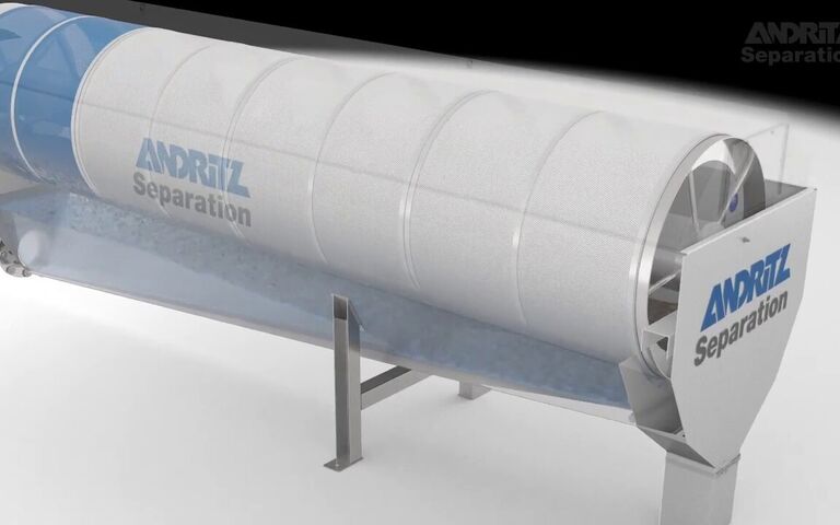
Centrifuges based on the solid bowl configuration are the most widely applied to sludge processing and are most often referred to as decanting centrifuges. They consist of a horizontal cylindrical−conical bowl, rotating at 1000−3500 RPM, with an Archimedean screw conveyor within the bowl which rotates independently of the bowl and at a slightly lower speed.
The difference in rotation speed between the screw conveyor and bowl is referred to as the differential velocity − the lower the differential rotation speed (or velocity), the drier the thickened product. Values between 1 and 30 RPM for the differential velocity are typical.

The aspect ratio (i.e. the bowl length to diameter) is in the range 2.5−4:1. The gap between the screw and the inner wall of the bowl is usually no more than 2 mm – sufficient to allow the passage of water while retaining the dewatered solids.
The pre-conditioned sludge is introduced to a rotating distributor section which directs the sludge into the annular gap between the screw and the bowl wall. The rotation of the bowl causes the particles to migrate to the inner walls of the bowl under the action of the centrifugal force.
The particles are scraped off the walls by the conveyor screw and transported towards the conical section to the thickened product outlet, often termed the beach. The water forms the centrate stream, which exits over an adjustable weir at the other end of the bowl if the centrifuge is configured for counter-current operation.
Solid bowl decanter centrifuge, GEA Group
Solid bowl centrifuge decanting centrifuge, Alfa Laval
| Sludge origin | Cake solids | Solids capture without polymer | Solids capture with polymer |
|---|---|---|---|
| Primary | 25−35 | 75−90 | ≥90 |
| Waste activated sludge (WAS) | 5−15 | 60−80 | ≥90 |
| Trickling filter (TF) | 10−120 | 60−80 | ≥90 |
| Anaerobically-digested (AD) primary | 25−35 | 65−80 | ≥85 |
| Anaerobically-digested (AD) WAS | 8−10 | 60−75 | ≥90 |
| Mixed, primary + WAS or TF | 12−30 | 55−65 | ≥90 |
| Mixed, primary + TF | 20−25 | 60−80 | ≥90 |
| Mixed, AD primary + TF | 18−25 | 60−75 | ≥85 |
| Mixed, AD primary + WAS | 15−20 | 50−65 | ≥85 |
Basket and disk-nozzle centrifuges
Basket centrifuge
A basket centrifuge is based on an upright rotating vessel (or basket) which can be either perforated or solid, with the solid basket type being the most widely used of the two in sludge thickening. The feed is continuously introduced into the centrifuge while the liquid (centrate) is removed via an overflow weir.
As a result of the removal of the liquid stream, the solids build up during centrifugation, forming a cake deposit that must be periodically removed. When the basket becomes filled with solids the centrifuge slows down and the upper semi-liquid soft cake layer is removed by skimming, which typically removes 5−15% of the solids. The remaining solids are dislodged periodically using a plowing knife moving into the slowly rotating cake, the solids being discharged centrally at the bottom of the centrifuge.
Basket centrifuges are typically operated at low centrifugal forces and have relatively low solid handling capacities. They can achieve high solids recoveries without chemical conditioning.
Disk-nozzle centrifuge
The disk-nozzle centrifuge consists of a stack of 50−150 inverted cones separated by ~ 2 mm. In this configuration, the solids pass down the channels formed between the adjacent cones under the action of centrifugal force, while the water passes to the centre. This configuration is rarely used for sludge processing since the 2 mm channels are subject to clogging by larger sludge particles.


